The purpose of this statement is to ensure that the reference electrodes when delivered to site are correctly connected to the cable supplied locally.
- The electrodes will be delivered calibrated ready for the cable connection.
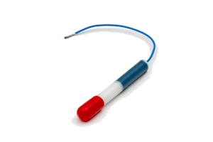
- The male spade connector on the silver wire of the electrode will be clearly visible in the body cavity.
- A cable end cap and a female spade connector for the cable will be supplied separately.
- The cable should be stripped back approximately 8mm and double crimped to the female connector with one crimp on the wire and the other on the cable insulation.
- The female spade connector is then push fitted to the male spade connector.
- The connection cavity in the electrode body should then be filled with insulating epoxy resin and the cable cap pushed into place over the end of the electrode.
Note: The maximum cable size is 1.5mm2 for the cable gland. Please check the cable size before ordering.
Download↓

 General Information