 General Information
 |
 |
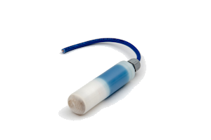
The purpose of this statement is to ensure that the reference electrodes when delivered to site are correctly connected to the cable supplied locally. The electrodes will be delivered calibrated ready for the cable connection.
The male spade connector on the silver wire of the electrode will be clearly visible in the body cavity. An IP68 cable gland and a female spade connector for the cable will be supplied separately.
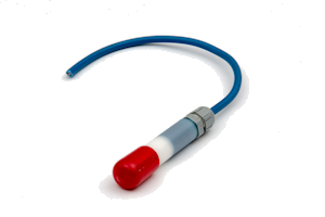
The cable should be stripped back approximately 8mm and double crimped to the female connector with one crimp on the wire and the other on the cable insulation. The female spade connector is then push fitted to the male spade connector.
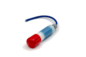
The connection cavity in the electrode body should then be filled with insulating epoxy resin and the cable gland pushed into place over the end of the electrode; the cable gland unit may require taping into position while the resin cures. The next day the cable gland can be tightened to complete the cable connection.
Note: The maximum cable size is 2.5mm² for the IP68 cable gland. Please check the cable size before ordering.