 Installation Instructions
Installation Procedures
The purpose of this statement is to ensure that the reference electrodes when delivered to site are correctly stored, checked for functionality and installed.
Storage
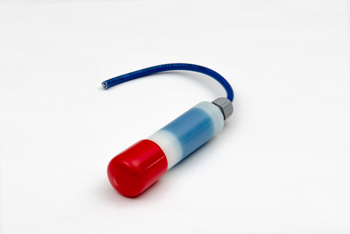
The electrodes are individually numbered and delivered to site boxed with the red protective caps in place. The purpose of the caps is to protect the sensor end of the electrode from contamination or damage whilst in storage.
With the delivery inside the box there will be a calibration certificate for all the delivered electrodes. This document should be kept with the record documents for the contract. The calibration certificate is a record of the individual reference potentials measured against a saturated calomel electrode (SCE) at 20°C under laboratory conditions.
The Corrosion Engineer may refer to the information on the calibration certificate during the operation of the monitoring system.
The electrodes should be checked to ensure that they match the order and stored with the red caps in place in a safe, dry place within a temperature range of 0°C and 45°C.
It is important to ensure that the electrode and its cable are protected from physical damage.
Pre Installation Functional Check
The purpose of this procedure is to check that the electrode potential is stable.
Prepare a solution of 3% salt solution; 30g of sodium chloride (salt) per 1 Lt of water. Remove the cap from the electrode and soak the tip of the electrode in the solution for a minimum of 2 hours and maximum of 3 hours
After soaking the electrode measure the potential using a calomel electrode (SCE) with a digital voltmeter at 10mohm and 1000mohm input impedance with the SCE connected to the positive/common terminal and record the results. The potentials should be steady and in the range +/- 20mv of the calibrated values.
A satisfactory alternative to using a saturated calomel electrode would be to check the soaking electrode potentials against each other or use one extra electrode as a test electrode.
Once the electrode is checked it should be removed from the solution, the cap carefully replaced and it should be installed within 48 hours.
Electrode Installation
It is recommended that the electrodes are positioned and installed in accordance with the international standard ISO12696:2016
Procedure :-
In some cases the concrete is cored and the electrode placed in the core hole with the concrete then made good. At other times, to ensure good contact, the electrodes are pre-potted in a mortar cylinder before embedding in the concrete.
The important points to remember are that the concrete should be pre-wetted , the red cap removed and the cable supported while the concrete is placed and cured. The electrode-measuring tip must be fully encapsulated by the repair mortar. Variations on this procedure can be acceptable subject to agreement by the Design engineer.